The History of Watermills
The first documented use of watermills was in the first century BC and the technology
spread quite quickly across the world. Commercial mills were in use in Roman Britain
and by the time of the Doomsday Book in the late 11th Century there were more than
6,000 watermills in England. By the 16th Century waterpower was the most important
source of motive power in Britain and Europe. The number of watermills probably
peaked at more than 20,000 mills by the 19th Century.
The Norman Conquest introduced the feudal system to the country and ‘soke rights’
forced everyone to have their corn milled at the mill owned by their Manorial Lord
which stayed in use until as late as the 19th Century. Although the “Right of Soke”
was never written in law, it was commonly practised in Britain – and throughout
Europe – until the 16th century, even after the country had moved away from feudalism.
Watermills continued to play an important role in British rural life and were in
growing demand, as improvements in farming techniques enabled farmers to produce
even more corn, which was being ground to make flour in local mills such as the
‘Old Mill’.
With agricultural developments at the beginning of the Industrial Revolution, people
began to move away from agriculture into other industries. The population began to
move to Britain’s growing towns and cities in search of the new jobs and by the
mid-nineteenth century Britain had changed drastically. The population had doubled
in less than 60 years, Britain was becoming increasingly urbanised and technology
was changing the processes of production.
There was a growing demand for flour within towns and cities and shortages developed.
To fill the gap, Britain became more reliant upon imported corn from countries such
as the USA and Russia. These imports were limited due to the unpopular ‘1815 Corn
Laws’, which placed quotas and levies upon the crop to protect British landowners
from competition. In 1846, the ‘Corn Laws’ were repealed, allowing unlimited imports
of the crop into the UK and this finally signalled the end of the water mill.
Large quantities of the crop were arriving in Britain’s ports and although water
mills were still being used during this period, they were coming under increased
pressure from the new steam mills. Despite initial problems with steam engines,
over the years they became more and more efficient. The new mills also favoured
a roller rather than the millstone that was used in water and windmills. The roller
had two advantages; it produced whiter flour, which was considered to be superior,
and it left less oil in the flour, so the bread lasted longer.
As the quantity of corn produced on local farms fell and the amount imported
increased, this combined with a growing demand for flour in towns and cities.
Land communications improved with the introduction of the railways which allowed
flour milled in the ports to be moved easily to the towns and cities where it was
needed.
Rural water mills began to close down to be replaced by the large, industrial,
port-based steam-powered mill and by the end of the 19th Century almost all rural
watermills had ceased commercial production.
Water mills use the flow of water to turn a large waterwheel. A shaft connected to
the wheel axle is then used to transmit the power from the water through a system
of gears and cogs to work machinery, such as a millstone to grind corn.
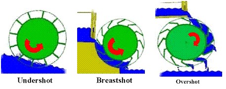
There are various designs of waterwheel, depending on the water supply available,
including undershot (water hits the wheel paddles at the bottom of the wheel),
breast-shot (water hits the wheel half way up) and overshot (water hits the wheel
at the top).
Watermills are usually built beside streams or rivers to use them as a water supply.
Very often these supplies were improved by the provision of mill races and weirs to
help overcome the problems of different seasonal water levels. Many of the weirs
seen on rivers today were originally built to help control water levels for watermills.
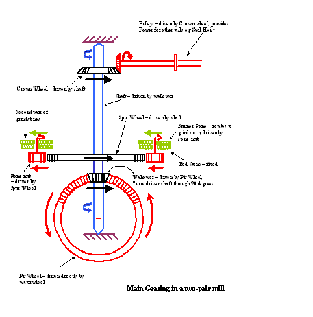
Usually power from the waterwheel was transferred to the inside of the mill by a
shaft extending from the waterwheel axle which connected to a large gear wheel
called the Pit Wheel (because half of it lies below the floor level of the mill,
in a pit). Power was then turned through 90 degrees by bevel gears to turn a large
vertically mounted shaft leading to the upper floor of the mill. At the lower level,
this shaft drove a large Spur Wheel, which then provided power to turn the millstones.
At the top of the shaft another large wheel, the Crown Wheel, was placed to drive
other machinery in the mill, such as sack hoists.
Millwrights were highly skilled craftsmen who could work with wood and iron to build
the complex working machinery of the mill.
Various hardwoods were used in the construction of the different parts. Cogs were
often applewood, hornbeam or beach. Wheels and shafts were oak, whilst treenails
(dowels to join wooden parts together) were holly. Elm, more resistant to rot, was
used to make the waterwheel paddles.
Later, when cast iron became available, this was frequently used for submerged parts
and larger gear wheels. Iron-to-iron gearing was avoided because of problems with
wear, and it was found that iron-to-wood gearing ran more quietly and was more
easily maintained. When size of castings was a problem, larger parts were often
composites bolted together – an example of this can be seen in the crown wheel lying
in the main room of the Old Mill.
Millstones were a vital component of the mill and had to be made from special hard
wearing stone which was not readily found locally. The Romans imported stone from
the Rhine Valley in Germany to England and during the Middle Ages the best stone was
sourced from France. By then, some stone was also becoming available from within
England, such as Millstone Grit from Derbyshire, because of the cost and slow
transport from abroad. As an example of the cost, imported millstones for a small
mill might cost more than a year’s wages for a skilled craftsman.
Millstones were fitted in pairs, the upper ‘runner’ millstone moving against a
lower fixed millstone. Stones were usually about 4 feet (1.25 metres) in diameter,
weighed more than a ton and were geared to turn at about 125 rpm.
Special patterns needed to be cut in the stones to grind the corn and the two stones
had to match each others shape very precisely. Highly skilled stone dressers were
needed to cut the stones correctly since wrongly set stones would produce flour that
was too fine from one side and too coarse from the other. They had to be kept full
of corn when running to keep the two stones apart – if the stone surfaces touched when
running then they could wear out in a few minutes compared with weeks of normal use.
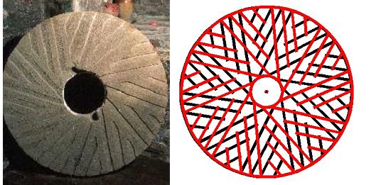
The photo shows the typical pattern cut into the millstone. The diagram on the right
shows how these patterns were put onto the static bedstone and the moving runner
stone in such a way as to cause lots of ‘crossing lines’ comparable to the action
of hundreds of pairs of scissors when the runner stone was moving, to produce the
grinding action. The angle of the crossing lines tended to push the grain towards
the outside of the millstones where the flour could be collected.
Because of the heavy wear and tear on machinery and the risk of fire from sparks to
the dusty atmosphere, the lifetime of mills rarely exceeded more than 200 years
before a new mill would be rebuilt over the same traditional site.

The process for grinding flint used flint nodules as the raw material. These nodules
first had to be calcinated by burning them in a Flint Kiln until they turned white
and had become more friable (crumbly) to allow them to be ground more easily.
The calcinated flint nodules were then put into grinding tubs with water and ground
for about eight hours to a thick creamy fluid. The grinding stone for flint mills
was chert – the nearest source for chertstone to Jesmond is at Richmond, North Yorks.
Flint grindstone did not have patterns cut into them like corn millstones – they
had a palin surface. The fluid was pumped across the yard to two vats in a drying
shed, the surplus water drained off the paste heated for about 24 hours until it
was thick enough to be cut into blocks. The blocks were carted to the Ouseburn
potteries to be used in the manufacture of glaze. Fragments of the chert grindstones
can still be seen at the Old Mill.
It is not known whether the Old Mill had its own flint kiln, or whether it brought
in calcinated flint from outside. A possibility is that the lime kiln marked on the
map of the Ouseburn Valley at Heaton Cottage was actually a flint kiln, or indeed
it could have been dual purpose – used for burning lime or calcining flint.
Although the main use of watermills was for corn, they could also be used to prepare animal feed, grind flint, drive water pumps or sawmills, as ‘blowing engines’ to feed air to iron forges and for stone crushing amongst other things. Modern Uses of Water Power : Hydroelectricity Today
The energy potential of moving water has been harnessed for thousands of years,
originally using water wheels to drive mills and machinery.
Today it is estimated that hydro-power produce one fifth of the entire world's
electricity. In emerging economies hydro is used to generate one third of the
electricity used. Canada, the USA and China are the three largest generators
f hydro electricity. Most large hydro stations have dams but thousands of small
hydro stations have no dams - they are 'run of river' and make a minimal impact
on the environment. There are hundreds of run of river hydro stations in the
developing world (of around 5 kW capacity)
A modern hydro turbine generator set can convert over 90% of the energy in the
available water into electricity. This is more efficient than any other form of
generation.
Small-scale hydropower is one of the most cost-effective and reliable energy
technologies to be considered for providing clean electricity generation.
The main advantages that small hydro has over wind, wave and solar power are:
In England the use of hydroelectricity is quite limited, however in Scotland it
produces 10% of the electricity generated.
Cruachan Power Station near Oban in Scotland can operate as a conventional hydro
plant but generally it uses off-peak electricity to pump water to its upper reservoir
in readiness for generating during demand peaks the following day. The station can
produce electricity for the grid in two minutes flat.
The Galloway Hydro Electric scheme, commissioned in the mid 1930s, was the first
large-scale integrated hydro-electric complex to be built in Britain for the
purpose of public electricity supply.
The scheme covers a large area in Galloway and South Ayrshire and consists of six
power stations, with a combined output of 106.5 MW, eight dams and a number of tunnels,
aqueducts and pipelines.
There are a number of other hydropower stations in Scotland.
The world's largest operational hydro plant is the ITAIPU project shared jointly
by Brazil and Paraguay - it has 12,600 MW of installed capacity.
Each year ITAIPU generates 75 TWh of electricity and avoids 67.5 million tons of
carbon dioxide emissions - compared to coal power plants. 26% of the electrical
power consumption of Brazil and 78% of Paraguay are supplied by ITAIPU.
Having more power than 10 nuclear power stations it has supplied the second
largest city on the planet with zero-emission electricity since 1984. The scale
of the power stations grew, with the final installation being March 1991. The
final cost of ITAIPU amounts to US$ 20 billion.
If the whole area of the lake - at nominal level - was covered by solar modules
the power generated would be 135 000 MWp, which would produce 230 TWh a year.
For the same yearly output as ITAIPU a solar PV-plant would cost US$ 132 billion.
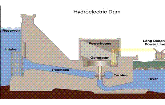
Although there are different forms of hydroelectric schemes, they all are based on
the following components:
This type of installation has very little impact on the environment, any dam is
quite small, usually a weir – little or no water is stored. This means that any
adverse affects are minimised.
The dam raises the level of the water to create a hydrostatic head; this is the
difference between the level of the water in the dam and the level where it flows
out from the scheme. This acts to trap the water and can be released when necessary,
enabling the water held to become stored energy. The height of water necessary to
exploit the resource varies from a few metres up to 2000m; the best results have
come from heights of 120m.